Sunday, October 29, 2017

Paper Fins?

A friend helped me make some 2" thick red oak planks for some outdoor storage shelves.  The planks were made from discarded timber cuts found at a local lumber mill.  I had to fill in some dry rot that was in one of the planks with an epoxy wood filler mix I made.

While I was at it, I decided to do a little experimenting with some (old) desk ink blotter (IB) paper I scored.  Figured it might make usable substrate for fin plates when saturated with epoxy.  The IB paper is very absorbent.  

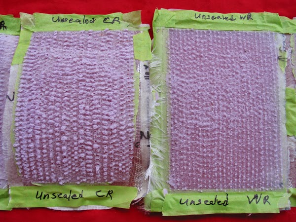
Four pieces of IB paper created a mini-panel (3" x 5") that is 3/32" thick.  (Almost didn't get the test piece out from between the glass panes.)

Even with the short pot life, Kwik Kick epoxy completely saturated the 4 pieces of IB paper before the resin began to set up.  I would want a bit slower set time when doing more than 4 pieces of IB paper in one sitting.

Got the test piece out this morning.  Seems pretty tough.  Couldn't break it with my hands/fingers.

Need to try laying up 16 pieces of IB paper next.  Might give it a FG skin/shell after foiling for greater strength.


Thursday, June 2, 2016

How Much Resin to Laminate a Surfboard

I laminated some 8" x 24" XPS foam test pannels a while back.  As a hack, the best I could do with 6 oz E-glass was 2.25 oz epoxy (resin + hardener "volume") per square foot of XPS.  As a hack, I suspect I would need more for PU and EPS.  For a 7-6 board, my number is very close to the high recommendation on the Greenlight Chart.  
Brian said his Greenlight Chart is for units of weight in oz.  Resin Research and Green Room epoxies can be mixed by volume, 100:50 (2:1) -- 100 oz resin by volume = 110 oz by weight; 50 oz hardener by volume = 49 oz by weight; 150 oz by vol of resin + hardener = 159 oz by weight.  Multiply (mixed) weight recommendation by 0.94 to get mixed "volume" of resin needed (150/159 = 0.94.)
My assumption for "estimating" surface area to laminate one side of a surfboard is that the surfboard is an ellipse that is 6" wider and 6" longer than the actual surfboard.  Surface area of an ellipse is 1/2 width x 1/2 length  x 3.1416 (pi).
Bottom line,  John Mellor's method and/or the GreenLight chart are a good place to start.  For a hack like me, I go with the highest recommendation plus a few extra oz.


"In the past, I used to recommend that people start their calculations with:  The length of the board, the weight of the cloth, and the number of layers.
Do the math and figure out the total weight of the cloth being used and multiply that by 1.5.   That should give you a ballpark estimate on how much total resin to use.
A 9 foot board will need about 3 yards of cloth.  If the cloth is 6 oz fabric and you're doing a double layer for the deck, the weight of the uncut cloth will be 36 ounces... less after you cut it to fit the outline.  Sooo... 36 X 1.5 = 54 ounces of mixed resin.  The Greenlight chart says 36 - 50 ounces of resin for the same glass schedule.  Close enough.
That's just my recommendation for a 9 footer, double 6 deck lamination and allows for some waste.  A beginner using MEKP catalyzed resin will likely find himself 'flooding' the board and squeegeeing off a lot of excess in an effort to save time.  If you're using UV catalyzed or epoxy resin, you will have more time and can get by with using resin more sparingly.  Epoxy is more expensive so there is definitely an argument for wasting as little as possible.  With epoxy blends of slow/normal cure times, a beginner has the luxury of not having to hurry like with MEKP catalyzed polyester."


Saturday, March 7, 2015

Modify Aquarium Air Pump for Vacuum: Whisper AP 150

Record cold weather, day job and family have put the XPS laminating tests on hold for the moment.  Last Friday 13 inches of snow shut down my little rural community.  The bright light reflecting off snow through my patio door was perfect for modifying an aquarium air pump though.

Gdaddy at swaylocks.com posted about how he converted a Whisper AP 150 aquarium air pump for suction.  He uses it for vacuum bagging composite laminations.  He used the same conversion method found at the following link, but for an AP 150.  Gdaddy reported he could get 10-11inches of vacuum pressure -- I will assume inches of "mercury."

http://www.instructables.com/id/Vacuum-Pump-from-Aquarium-Air-Pump/

The pump he modified had a similar internal pumping configuration as this one:

http://cdn.instructables.com/F49/J0QJ/GHFK7LR8/F49J0QJGHFK7LR8.MEDIUM.jpg


The Whisper AP 150 is a diaphragm pump made for use in deeper water, reported to work at a water depth of 96 inches.  I bought two of the new Whisper AP 150 air pumps on the internet for a good price last year.  When I opened them up for conversion, the new 150s had been re-designed (pictures below) since the older AP 150 model Gdaddy used (above).

If you have the patience for disassembly, modification and re-assembly; the Whisper AP 150 shown below can be modified for suction with minor changes.  I did it last Friday (03/06/15).  Rather than blowing air, the output jet now sucks air.  (I am assuming the newer AP 300s have the similar center plate diaphragm mounting configuration),


New Whisper AP 150 aquarium air pump


View of internal works -- electromagnet, armatures, armature magnets and diaphragms.


Armatures with magnets and diaphragms extended to expose clear plastic valve housings.


AP 150 with internal works removed from housing.


Close-up of clear plastic valve housing in normal position, electromagnet on the right.


Tools for modifying the pump for suction/vacuum; hacksaw blade, small file, Phillips head screwdriver, Q-tip and vaseline.  Vaseline makes re-installing diaphragms much easier.


Side view of internal works with clear plastic valve housing in normal position, electromagnet on the left.  Note groove over black plastic ridge at bottom right of valve housing.


Close-up of clear plastic valve housing in normal position, electromagnet on the left.  Note groove over black plastic ridge at bottom right of valve housing.  Remove screws from valve housings with Phillips head screwdriver.  Remove clear plastic valve housings and cut new grooves with hacksaw blade and small file.


Modified clear plastic valve housings with new grooves (one each) to allow 180 degree rotation from normal position.


Close up of clear plastic valve housing rotated 180 degrees from normal position.  Note cut groove added is over black plastic ridge at bottom right of valve housing.  Fully visible translucent valve flapper is closest to the electromagnet.  With clear plastic valve covers each rotated 180 degrees, the Whisper AP 150 will now suck air through the nozzle where air was previously discharged for delivery to aquariums/aquatic tanks.
_____

Below are pictures of the bottom of the AP 150 the round plastic piece is the air filter cover/retainer. The white pad is the air filter.  When functioning normally, air intake is through retainer and the filter.  But when modified for suction air is discharged through the filter and then the filter retainer.  I found that by removing the retainer and filter that air discharge from the pump housing was improved.  And as a result of reduced resistance to air discharge, I could feel an increase in suction.  I will probably increase the diameters of the 4 holes in the bottom below where the filter was formerly placed -- to reduce air discharge resistance further and hopefully improve suction a little more.


Circular air filter retainer is attached to the bottom, holding the filter element in place.


Air filter retainer and air filter element are removed.  The four holes in the housing bottom that facilitate air flow are visible.  Normally they are covered by the filter and retainer.  Removing the filter and retainer reduces resistance to air flow.  Since air is now being discharged through the 4 bottom holes, the air filter serves no practical purpose.  Enlarging these 4 holes will likely reduce resistance to air-flow discharge further.


Monday, January 19, 2015

Circular Velocity/Acceleration in Ocean Waves & Surf Physics

Below are some figures/diagrams of circular velocity and acceleration. Circular/elliptical motion is observed in the water movement of deep and shallow water ocean waves.

Related links:

http://highered.mheducation.com/olcweb/cgi/pluginpop.cgi?it=swf::640::480::/sites/dl/free/0072826967/30425/14_04.swf::Fig.%2020.4%20-%20Orbital%20Motion%20in%20Shallow%20Water

http://www.acs.psu.edu/drussell/Demos/waves/Water-v8.gif
http://www.acs.psu.edu/drussell/demos/waves/wavemotion.html

The green line is the relatively constant velocity of the ocean water moving along its circular or elliptical path.  The left and right walls of the square/rectangle describe the vertical motion at the front and back of the wave, respectively.  The top and bottom 
of the square/rectangle describe the horizontal motion at the top and bottom of the wave, respectively.


Circular Acceleration & Velocity


Elliptical Acceleration & Velocity


Red and Blue lines show how velocity changes in the vertical and horizontal dimensions.


Surfboard Trim Dynamics


My latest grapics.
In order to take off, the surfboard must achieve wave(form) speed (C) before the wave passes under the surfer.  Wave slope affects the time (t) required to achieve C.  The surfboard's shoreward speed (Vs) must be Vs = C to remain in trim.  The surfboard's transverse velocity (Vt) along the wave's face must be greater than or equal to the transverse velocity of the breaking crest (Vbc).  After the wave has been caught, if shoreward surfboard velocity (Vs) drops below wave speed (C), the wave will pass under the surfer/surfboard leaving the them both behind.

I think many mistake the angle of the surfboard relative to the X axis (transverse movement viewed from the shore) as the angle that affects the continued forward velocity.  The angle of the wave face slope relative to the Z axis (direction of forward/shoreward movement) provides the acceleration needed to maintain continuous critical velocity (gravity).  The slope of the face is the curved ramp (inclined plane).


The colored curved lines below represent the slopes of three waves, red being steepest and blue gentlest.  The colored vertical lines, tangential to the top of each curve, represent the wave height.  The long black arrow represents the point on the wave face where the surfer achieves a shoreward velocity equal to wave speed (C) on take-off.  For an individual/independent wave, it could also represent the point where wave slope provides the angle necessary to create the acceleration needed to maintain a shoreward speed (Vs) equal to wave speed C (necessary for trim).


The point where the velocity arrow intersects the curve on each wave is also representative of the horizontal distance traveled, and therefore, the time required to achieve waveform speed C, dropping down from the crest.  The length of the slope curve decreases as wave slope increases.  Net acceleration increases as slope increases (curved ramps/inclined planes).  Position on the wave-face slope determines where the shoreward velocity reaches C.

I didn't add labels to the axes because I would have had to reduce figure size to fit them in.  The figure would get a bit busy to look at with added labels.


Tuesday, December 16, 2014

XPS Peel Panel Tests

XPS Tests

(See 1 January 2018 update at bottom of this post)

I have been meaning to do some XPS testing for a while now.  A cold autumn day seemed like a good time to do it.

BSD's thread about sealing XPS for PE motivated me to start the tests today.

I only had time for the first half of the first test.  My objective has been to improve epoxy bonding with XPS.  A thin, low viscosity coating is what I was thinking about.

Simple tools and common materials.  Things you might find in the shed.

I cut a small XPS test panel 8" x 24" from a low density sheet of pink residential insulation (Owens-Corning); marked off four 8" x 6" quadrants and sanded with four different grits (150, 100, 60 & 40).  

I added the first coat of Secret Sauce a couple hours ago.  The sealer disappeared nicely into all the sanding grooves.  I will add another coat of sauce later tonight.  Looks good so far...Epoxy test glassing will have to wait until next weekend.


A strong shell with higher densitiy foam should be better for XPS rather than using low density foam.

First I want to do the peel test to see how much "low density foam" pulls loose with the glass.

Hopefully low viscosity sealant will penetrate the surface layer of small ruptured cells, and the higher surface area of finer grit sanding grooves, better than the higher viscosity epoxy resin does.

The first coat penetrated all roughed surfaces nicely.

I will add another coat then sand with 150 grit and do the test lamination with epoxy. 

I will need to get some of the new Dow blue mix -- less than 10% styrene polymer with 60-90% propenenitrile ethenyl benzene.  The O-C pink is about 80-95% styrene polymer.

After that, side-by-side comparison with sealed-sanded and unsealed-sanded XPS.

I applied the second coat of Secret Sauce last night.

Observations:
- The first coat dried nicely after a few hours.  All surfaces looked good.

- The foam applicator worked well for adding a second coat to the 100 & 150 grit surfaces.

- Adding a second coat with the foam applicator to the 40 & 60 grit surfaces felt like I was sealing coarse sandpaper.  I was worried I was going to rip out small chunks of applicator foam.  I did not notice any small pieces in the finish.

I may need to look at applying the sauce with a 0.25" nap roller for coarser surfaces.  I decided not to for this first test because it looked like the roller might lay down too much sauce.

I have seen several methods mentioned for improving epoxy-XPS bonding, including razor cuts.  This guy claims he tried several methods.  He says he got best bonding by "scoring" foam with a steel-toothed pet brush -- using 30 psi min. comp. strength O-C XPS:

http://ecomodder.com/forum/showthread.php/improve-bond-fiberglass-epoxy-home-depot-foam-extruded-24820.html

As with histology (internal surface area of the small intestine) and oxygen transfer in water (bubble size), surface area to volume ratio increases as object size decreases and number increases.  Hopefully, this will hold true for some given groove size (peaks and valleys) from sanding.

The trick is finding a bonding agent that will fully penetrate these grooves.  Maybe exterior, water-based polycrylic concrete/tile sealer will do that, creating a thin intermediate layer between epoxy and foam sanding grooves.

I just re-read this and realized what I said.  The "groove penetration" argument is bovine manure.  Barring differences in inter-atomic/inter-molecular forces, there should be no difference in epoxy penetration for grooves of the same size (polystyrene vs. polycrylic).

The big difference is porosity, "closed" cell vs. open (XPS vs. EPS), and resulting epoxy penetration.  Another possibility would be a difference in the strength of bond type (hydrogen, dipole, ionic, covalent, etc.) between XPS and polycrylic vs. epoxy.

More later...

Surface roughness (epoxy surface penetration) is an issue with XPS.  XPS is "closed cell" foam.  It absorbs very little water (virtually no water).  The gas bubbles in the foam are very small and closed (no interconnecting air passages like EPS has).  The only way gas can be released is if the cells are ruptured.  Even after sanding, the surface is not porous, just a thin surface layer of very small ruptured cells. As a result, the epoxy has very little surface area to bond with and virtually no foam penetration (no soaking in like in EPS).

First, delamination of XPS is related to foam density and epoxy penetration.

Lower density foam crushes (compression) and tears (shearing).I do not want to write a treatise on this.  

I will try to keep it brief.  Epoxy bonding is related to the material surface energy (adhesion/wetting) and epoxy penetration into the surface profile (roughness/porosity).  Surface roughness increase bonding surface area and more mechanical interlocking with the surface.

Epoxy has a surface energy around 45 dynes/cm.  Epoxy will bond better with materials have surface energy values greater than or equal to 45 dyne/cm.

The greater the viscosity of the coating the lower the surface penetration.

I am using the lower viscosity polycrylic sealer because it can penetrate deeper into the XPS surface -- into smaller grooves. pores and cells.  The idea is to get a layer that has deeper penetration and more anchoring than the higher viscosity epoxy would have.   Then bond the epoxy to this thin, anchored intermediate layer.  I am assuming the sealer has better strength than the XPS.This explanation is a bit generalized."Stoneburner,A surface energy of 45 dynes/cm?  What does this refer too? Mike"It is an abstract concept that I have a very limited grasp of.  It is related to the energy needed to create and maintain a surface -- like the formation of a water drop.  All materials with surfaces have it.  For fluids, it indicates how well a fluid will spread/wet-out on solid surfaces. Here is a definition from Wikipedia:  
  1. Surface energy, or interface energy, quantifies the disruption of intermolecular bonds that occur when a surface is created.  Surface energy is conventionally defined as the work that is required to build a unit area of a particular surface.
I was not really aware of it until I started learning about how epoxy bonds with surfaces.  All compounds with surfaces have their own unique surface energy value (polyethylene = 32; polystyrene = 34; 6,6 nylon = 42; glass = 250-500; etc.).

I have some links about epoxy surface energy and its bonding that I could give you.  

The take away is that epoxy adheres better with solid surfaces that have surface energy values equal to or greater than 45 dyne/cm.

I read somewhere that others have used low viscosity epoxy for the first coat to get better surface penetration and then use higher viscosity epoxy for the second coat.  I do not think they were board builders.It seems like the keying done (below) with that steel-tooth pet brush could add a lot of epoxy weight to the build.

http://ecomodder.com/forum/showthread.php/improve-bond-fiberglass-epoxy-home-depot-foam-extruded-24820.html


Well I finished laminating the test panel just before noon.  Used an old 30" x 48" piece of 6-oz e-glass thas been lying around in a drawer for years. Laminated with some old RR Kwik Kick I need to use up.  I still have enough of both for several more tests.I am skeptical about the sealer.  

I am not sure whether two coats of sealer and sanding all sealed surfaces with 150 grit was the right move.  But I will know when I pull the glass tomorrow pm or Monday and see how much foam comes up in each quadrant.

I got a carpet seam roller and have a Woodpecker covering/perforation (roller) tool on the way.  The Woodpecker tool is an interesting tool I stumbled across while searching the internet.  It may have potential.  I have many more combinations of variables to look at now.


I discoverd the propenenitrile ethenyl benzene in the new DOW blue mix is also called styrene-acrylonitrile (SAN).  The surface energy value I finally found for SAN is 40 dyne/cm.  Much closer to epoxy's 45 than styrene's 33.  Depending on the amount of SAN in the mix, the new DOW blue should bond better with epoxy than polystyrene does.

I ran a concurrent test with my updated "low budget" resin warmer this morning too -- worked great.  I will post pictures and a description in this thread also.I got my Woodpecker tool in the mail today.  I played with it on a piece of scrap XPS.  I rate it as having very high potential for improving epoxy bonding with XPS.  Paid $10.00 + $3.50 shipping on Etsy, a bargain -- like new.  Stoked.

I peeled the glass from the XPS last night.  I needed good natural lighting for decent pictures.  Hopefully the right lighting today...

Portable, adjustable glassing stand (aka ironing board)


All quadrants simultaneously laminated with the same batch of resin


Peels from XPS surfaces sanded with 40-150 grit:150-grit surface


100-grit surface


60-grit surface


40-grit surface


Another view of XPS surfaces sanded with 40-150 grit:150-grit surface


100-grit surface


60-grit surface


40-grit surface

_____

@ Lemat -- I do not have the time or equipment/money for 4-point bending tests.  I believe that low density/low min. compressive strength XPS foam tests should give me some usable information about adhesion between epoxy and XPS.

@ Dr. Strange -- I peeled several PU/PE longboards in the past.  I was surprised how little foam was pulled up.  I still had plenty of good foam to work with.  Funny you should mention EPS, I have been planning to play with Secret Sauce on it too -- different reasons.

@ Barry Snyder -- No surprises.  The greater irregular bonding surface created with coarse sandpaper caused more foam to pull up than with higher grit surfaces -- better anchoring.  Yeah, I really want to try the perforation rollers next.

@ John Mellor -- Agreed.  Sealed vs. unsealed was/is the central objective of the tests. The initial hypothesis was/is sealer will improve epoxy adhesion with XPS.  The null hypothesis is sealer will not improve epoxy adhesion with XPS.

For the first test, I was more interested in seeing whether the polycrylic sealer would bond with XPS and whether epoxy would bond well enough with the sealer.  The results suggest epoxy adhesion with sealer is stronger than sealer adhesion with XPS.  Side-by-side sealed vs. unsealed is definitely needed.  I decided that looking at different grit effects in this preliminary bonding trial could also get me some surface roughness information at the same time.
_____

Observations

*  The 1.5 pcf/15 psi XPS insulating foam clearly tears and crushes very easily.  I can see how adding a wood veneer (Lavarat) or cork skin (melikefish) to the foam surface would minimize surface damage by dissipating/dispersing point impacts over a broader area.

*  Notice the greater amount of foam on the (numbered) edge opposite the side used to peel up the glass patch.  The peel edge was taped to avoid this effect.  The opposing/numbered edge without tape -- with resin drip over the foam edge -- appeared to have much greater mechanical bonding/leverage (bottle-opener effect?).

*  Uniformity -- while coarser grit appears to improve adhesion, it lacks uniform distribution over the entire surface.  The deeper grit cuts pulled up the most foam.  But the deeper cuts are random with gaps between them (areas of lower bonding?).

I believe perforation rollers could create more uniform mechanical bonding over the entire foam surface to be glassed.

I think I will look at the effects of perforation next.  Sealed vs. unsealed?  What final sanding grit before perforation?  Too coarse, and the deep sanding grooves will likely impact the effects of perforation -- especially uniform distribution effects.

Adding perforation rollers for testing too has significantly increased the number of potential variable combinations...
_____

As mentioned earlier, we still need unsealed vs. sealed comparisons.  There is a wide range of variables to play with.  It would be better for you to pick the combinations that interest you.  I welcome any test data you are willing to collect and bring to the table.

Here are a few potential variables to combine for testing:

* Dow (blue) vs. Owens-Corning (pink) foams: SAN + styrene vs. styrene, respectively = 2

* Foam min. compressive strengths (psi):  15, 25, 40, 60, 100 = 5

* Final sanding grits:  40, 60, 100, 150 (more?) = 4+

* Sealed foam vs. unsealed foam = 2

* Sanded sealer vs. un-sanded sealer (different grits too?) = 2

* Sanded foam vs. unsanded foam = 2

* Perforating rollers:  Woodpecker vs. Carpet Seam Sealer = 2

* XPS vs. EPS = 2

I am sure there are several more that I have omitted in the moment.  
Please use combinations that interest you.

For now, I am only testing four (4) treatments at a time with my quadrant panels.  Carefully selecting the right variable combinations can eliminate the need for testing all variable combinations.  For example, I want to look at perforation roller effects next:

* Perforating rollers:  Woodpecker vs. Carpet Seam Sealer = 2

* Sealed vs. unsealed  foam = 2

* Sanded sealer vs. un-sanded sealer = 2

* perforation before sealing vs. peforation after sealing = 2

* potential sanding grits for final foam surface prep: 150, 100, 60, 40 = 4

I can think of a few more variables for "roller testing" alone but am ignoring them for the time being.

Please correct me if my ancient recollection about this calculation is wrong.  If I remember my math correctly, the number of possible variable combinations/treatments for roller testing alone would be:

2 x 2 x 2 x 2 x 4 = 64

I only have 4 test patches in my next panel (limited by scraps) at the moment -- a big panel would be cumbersome to laminate on an ironing board.  So these are the first variables I will choose:

* I have plenty of low-density, pink O-C XPS to work with = 1 variable (all treatments)

* I will use 150 grit for final surface prep = 1 variable (all treatments)

* Sealed foam vs. unsealed foam = 2 variables

* Perforating rollers: Woodpecker vs. carpet seam roller = 2 variables

I will use the 150 grit to minimize sanding groove interference with perforation effects.I think I can get a good idea overall about sealed vs. unsealed effects on this one and will have eliminated one surface grit to test.

I still want to the test the effects of peforations made before and after sealing -- 2 more variables.  Next round...
_____ 

I was planning to color some polycrylic sealer with RIT fabric dye for use on EPS this weekend.  My original thought was using the concrete sealer on EPS as a lightweight low viscosity sealer that would penetrate deeper into EPS than epoxy without adding a lot of weight.  It would also prevent too much epoxy from soaking into the foam.  But the main idea was to make the EPS more water tight in the event of dings -- especially lower density EPS foam.

Next, I thought maybe adding dye to the sealer might be an interesting technique for coloring EPS foam, creating a unique mottling pattern with the styrene beads.  Last weekend it suddenly ocurred to me that I could determine the degree of sealer penetration into EPS foam using the dyed sealer.  Degrees of penetration could be controlled by application method (foam pad, nap roller, brush, etc.) and/or timed surface flooding of the EPS.

Ironically, it never occurred to me to use the dyed sealer on sanded/roughed XPS surfaces to observe penetration.  I have a bottle of teal and a bottle of blue RIT dye.  I can get one more round of testing from the first XPS panel now.  More basic experiments.  Love it...
_____

I suspect many of the XPS failures can be related to the use of low density/low compressive strength foam (e.g. 1.3 pcf or 20.8 kg/m3).I have posted the specifications for commonly available XPS foam, Dow Blue and Owens-Corning Pink, at this link:

http://bgboard.blogspot.com/2013/12/polystyrene-foam-types-and.html
_____

For statistically valid comparisons, replication is needed to get a large enough sample size.  My number does not include replication for statistical analyses.

My testing here is about feasibility and at this time is not replicated.  Feasibility trials can be a good way to cull and select variables/treatments for further testing.

I am only speculating about the dried weight of a thin, single coat of concrete sealer.  I am assuming a thin coat concrete sealer becomes lighter after application because drying (evaporation?) seems to be involved.   At some point, I plan to weigh a piece of foam before and after sealing with polycrylic, but before lamination.  
_____

XPS Dye Test

XPS panel with 60-150 grit sanded then dyed polycrylic sealer surfaces + sanded, Woodpecker Roller peforated, then dyed polycrylic sealer surfaces -- 4 oz of polycrylic sealer was dyed with 15 ml of dark green, liquid Rit Dye.


Dyed 150 & 100 grit surfaces


Dyed 100 & 60 grit surfaces


Dyed 60 & 400 grit surfaces


Dyed XPS X-Sections

The natural lighting late Christmas afternoon was good enough for some cross(X)-section photos of the dye panel.  Dye penetration on the sanded surfaces is barely detectable to the un-aided eye on the 40-grit surface and "maybe" the 60-grit surface.  The much deeper Woodpecker perforations stand out noticeably in contrast.  The Woodpecker tines are approximately the thickness, maybe slightly thicker, of a single-edge razor blade and slice nicely into the foam surface.

Dyed 40-grit surfaces, most of the deep Woodpecker tine perforations noticeable on bottom surface
(Some dyed grit grooves barely visible  on top surface.)


Dyed 60-grit surfaces, deep Woodpecker tine perforations noticeable on bottom surface

(Some grit grooves maybe visible on top surface in second picture?)


Dyed 150-grit surfaces, deep most Woodpecker tine perforations noticeable on top surface

(No grit grooves visible on surfaces.)


XPS Perforation Tests

Problems that popped up were related to uniformity and depth of perforations (first photo below),  It was very difficicult to maintain even pressure across the whole carpet seam roller, getting half deep holes and half shallow holes.  I had to over-perforate with the carpet seam roller: I feel like the holes were too deep which caused too much foam "crushing."  There is an obvious learning curve for the carpet seam roller -- maybe Lavarat can offer some guidance.
I laminated the perforation test panel yesterday afternoon,  I will peel the glass late tomorrow afternoon.

The Woodpecker perforator made smaller, nice clean deep holes and was much easier to control.  Of course, I got a lot of practice with it perforating both sides of the first test panel before dying.
The experiments will continue...

XPS test panel sanded first 100 grit then perforated with Woodpecker (small holes) and Carpet Seam (larger holes) rollers -- left 2 quadrants sealed with polycrilic concrete sealer after perforation; right 2 quadrants are unsealed.


Perforated, sealed


Perforated, unsealed


_____

Here are some quick shots from my son's camera phone to ponder.

The close-up, money shots will have to wait for some good lighting -- hopefully tomorrow...

Foam side of the peeled glass patches:  left 2 patches, carpet seam roller; right 2 patches, Woodpecker roller.


XPS test panel surface after the laminated glass was peeled:  left half was sealled, right half was unsealed.


_____

XPS Woodpecker Roller (WR) and Carpet Sealer Roller (CR) Peel Test Photos:  Sealed vs. Unsealed

(Discussion & observations later...)

The money shots:

Perforated XPS, all quadrants laminated with the same batch of epoxy


Left half of panel:  sealed CR and WR quadrants, respectively


Right half of panel:  unsealed CR and WR quadrants, respectively


All quadrants peeled:  left to right -- sealed CR & WR and unsealed CR & WR (all foam side up)


XPS panel:  peforated surface after peeling


Sealed CR (left) & unsealed CR (right)


Unsealed CR (left) & unsealed WR (right)


Unsealed WR (left) & sealed WR (right)


Sealed WR


Unsealed WR


Sealed CR front, unsealed CR back


Unsealed CR front, sealed CR back


01 January 2018

It has been a few years.  In retrospect, I abandoned the sealer -- filled the roughed peaks and valleys without adding any apparent improved bonding with epoxy.

I liked the Topflite Woodpecker tool best.   Perforation is more about increasing surface area for bonding – many smaller holes/cuts would bond better than fewer big holes. The big holes add more resin weight. In my testing, the stock Woodpecker tool (WPT) seemed as effective as, or more so than, the carpet roller and appeared to use less resin (lighter?). I modified the Woodpecker tool, adding more tynes -- photos below -- to increase perforation numbers and total surface area for resin penetration/bonding. I had planned to use the modified WPT for a late summer-autumn build this year. But several issues postponed that project.  

Modified and Standard WPT.
(Standard WPT @ bottom of first two photos)